
All About the Level of Development (LOD)
- By Tarek Ghazzaoui, Eng. (senior BIM manager)
- on
Overview
Communication is key in construction projects, throughout all of its phases of design, construction, and operation. Communication is the double edge sword that can guarantee success or failure, depending on how it is used and the extent to which it is used. In the context of BIM, it is not limited to correspondence, but to greater project-related communication, such as design intent, design review (markup), constructability and operations & maintenance, among others.
One particular instance of interest of this communication is the Level of Development (LOD), which is a specification on BIM projects for geometric and information development of elements. At its core, the LOD specification merely serves as a technical communication tool between project stakeholders as to what the expectations are for the development of BIM models and how it can help with their intended use. This article will investigate this LOD specification and discuss everything about it, including what it is, why we need it, where it is specified, its benefits, its levels and how it is used on projects.
Let’s start with the definition.
Table of contents
Note: Click to go to a specific section.
What is Level of Development (LOD)
There are several definitions of Level of Development (LOD) in the industry, with some basic variances between them. There is also a difference between the American and British definitions of LOD, which will be discussed later in this blog article. However, the concept of LOD and its scope remains the same no matter which industry or market you work in.
In clear and basic terms, here is how I would define the Level of Development:
The Level of Development (LOD) is the specification for the 2D and 3D representation of elements along with their associated information in BIM models at a certain point in time; this is useful for many purposes during the project design, construction and operation phases.
In other terms, here is how different sources would define the Level of Development:
According to BIM Forum (source: BIM forum):
“The Level of Development (LOD) Specification is a reference tool intended to improve the quality of communication among users of Building Information Models (BIMs) about the characteristics of elements in models. The LOD Specification expands upon the LOD schema developed by the American Institute of Architects (AIA) for its E202-2009 BIM and Digital Data Exhibit and updated for the AIA’s G202-2013 Project BIM Protocol Form1 by providing definitions and illustrations of BIM elements of different building systems at different stages of their development and use in the design and construction process.”
According to AIA E202 contract document:
“Clause 1.4.4 Level of Development. The Level of Development (LOD) describes the minimum dimensional, spatial, quantitative, qualitative and other data included in a Model Element to support the Authorized Uses associated with such LOD.” (source: help.aiacontracts.org)
According to United BIM (source: United BIM):
“Level of development (LOD) is a set of specifications that gives professionals in the AEC industry the power to document, articulate and specify the content of BIM effectively and clearly. Serving as an industry standard, LOD defines the development stages of different systems in BIM. By using LOD specifications, architects, engineers, and other professionals can clearly communicate with each other without confusion for faster execution.”
According to Srinsoft (source: Srinsoft):
“BIM Level of Development (LOD) is an industry standard that defines how the 3D geometry of the building model can achieve different levels of refinement, is used as a measure of the service level required. These development models are purpose built for various stages of design, 3D visualization, construction-caliber quantities, scheduling, estimations, on-site production control and fabrication. Using the Level of Detail (LOD) industry specifications as a guide, SrinSoft’s 3D Modeling Service will create a 3D model of your projects based on the specificity required. We also deliver animation services for LOD in the sequence for virtual construction sequencing and simulation to develop insights of how and what will be constructed.”
According to the U.S. General Services Administration (source: GSA):
“Level of Design / Development / Detail (LOD) is the overall state of your information model at a particular point in its design process. This includes not only graphical objects, but also the data associated with the objects. Your model should develop over time from a very coarse design to the record drawings and as-builts. This process has been distilled down into five distinct categories as formalized in the AIA E202 contract document.”
So, as you see, the definitions are overall the same, with some minor differences which I hope will be clarified in the next sections.
Let’s discuss next why we need LOD on projects.
Why we need LOD

Some BIM professionals debate this point and question the need for a specification of this nature on projects. Do we need LOD specifications on projects? In my opinion, the short answer is yes, and here’s why.
According to the GSA (source: GSA):
It is critical to have a clear definition of what is included in the information model at different points in a project’s lifecycle. Understanding expectations, roles, and responsibilities is one of the most important aspects of a successful BIM-based project.
I totally agree with this point above; we need LOD specifications to ensure that everyone is on the same page in terms of expectations, roles and responsibilities regarding the development of BIM models (and their elements.)
1. Define overall LOD and list exceptions
Define a general LOD for all model elements (i.e. LOD 300), and list the exceptions as detailed as possible. This is a short and clear way to serve a blanket expectation of an LOD level, and list the exceptions in a table (i.e. LOD 100 for structural foundations, footings, piles and retaining walls, LOD 200 for shear walls and load-bearing walls, trusses and braces, etc.)
2. Define every element category in an LOD matrix
Define a detailed LOD matrix for every model element category, or group. This is usually based on industry standards, such as Uniformat, Masterformat and Omniclass, and sometimes on a list that’s not based on an industry standard provided by a project stakeholder. The latter however is not recommended.
In this case, where a detailed LOD matrix outlines the LOD specifications, it is important to note that it should not be based on a specific software’s categorization or classification of elements (i.e. Revit categories). It should be based on an industry standard, such as Uniformat, Masterformat or Omniclass, which is software-agnostic and can be used in the project design, construction and operation phases.
Where we specify LOD

That’s an important question. The LOD specifications serve two purposes on construction projects: contractual and operational. The following are the places where LOD specifications should show up on projects:
1. Proposal – optional (preliminary framework for contractual use)
An LOD matrix sometimes figures in proposals for professional services on construction projects, although this is not standard practice. It really boils down to the BIM-savviness of the owner and the set project requirements, the type of project and the intended use downstream (i.e. in construction and operation).
2. Contracts (contractual specification)
An LOD matrix can be attached as an annex to the contract as an integral part of it, to contractually bind project stakeholders to a commit to their LOD specifications obligations. Again, just like for proposals, there must be a need to add this contractually, which is the intended use downstream in construction and operation.
3. BIM Execution Plan (operational specification)
An LOD matrix can be attached as an annex to the BIM Execution Plan, to operationally outline what LOD levels are expected from different project stakeholders. This use of the LOD matrix is strictly for operational purposes, and it is usually based on the contractual agreements between stakeholders.
The LOD matrix is usually provided in Excel format and it is recommended that it contain the following information (the names of the tabs can be different as long as the content is covered):
- INTRODUCTION TAB - This tab should outline the author and manager of the LOD matrix, a revisions/versions log, acronym definitions (i.e. MEA = model element author) and general notes (i.e. the specific applications of the document, sources, etc.)
- LOD SPECIFICATIONS TAB - This tab should list the classes, groups or divisions of the LOD matrix (based on Uniformat, Masterformat or Omniclass) in its rows, and the LOD level and MEA per project phase in its columns.
- DEFINITIONS TAB - This tab should list the definitions of each LOD level used. This tab serves as the basis for the common understanding of project stakeholders on what each LOD level represents for the project.
Some sample LOD matrices are provided in the Resources section of this article for reference.
The benefits of LOD

There are several benefits for defining and using LOD specifications on projects. In my opinion, the best expression of the benefits was stated by BIM Forum’s Level of Development Specification (2015) report (source: BIM International), which states the following:
- To help teams, including owners, to specify BIM deliverables and to get a clear picture of what will be included in a BIM deliverable
- To help design managers explain to their teams the information and detail that needs to be provided at various points in the design process, and to track progress of their models
- To allow downstream users to rely on specific information in models they receive from others
- To provide a standard that can be referenced by contracts and BIM execution plans
Although LOD can be beneficial, it can also prove counterproductive if used incorrectly, interpreted “to the T” or misinterpreted. It is important to avoid getting lost in the weeds of modeling elements exactly based on the LOD definitions and constantly validating those definitions between project stakeholders. The primary focus of project stakeholders for using LOD specifications at any project phase should be on what information is to be included in model elements and how will this information be used in the current and future project phases.
The primary focus of project stakeholders for using LOD specifications at any project phase should be on what information is to be included in model elements and how will this information be used in the current and future project phases.
Tarek Ghazzaoui, Eng.
Senior BIM Manager
LOD levels explained
So now that we discussed what LOD is, why we need it, where we specify it and its benefits, let’s discuss the core of this LOD business, which is the LOD levels. I will discuss UK-related LOD topics in a section below, so the definitions and explanations below apply to American standards only.
In very simple terms, here is a general indication of the different LOD levels:
LOD level
Purpose
Description
Project phase
LOD 100
Pre-design or concept
Conceptual geometry / information
Schematic Design (SD) phase
LOD 200
Detailed design
Approximate geometry / information
Design Development (DD) phase
LOD 300
Construction details
Exact geometry / information
Construction Documents (CD) phase
LOD 400
Fabrication & assembly details
Fabrication-level geometry / information
Construction Documents (CD) phase
LOD 500
As-built details
As-built level geometry / information
Construction Administration (CA) – At handover
Some sources also add other levels:
- LOD 350 - This is similar to LOD 300 but, but it also “interfaces with other building systems.” (source: BIM forum). What this means is where “parts necessary for coordination of the element with nearby or attached elements are modeled. These parts will include such items as supports and connections. The quantity, size, shape, location, and orientation of the element as designed can be measured directly from the model without referring to non-modeled information such as notes or dimension call-outs.” (source: BIM forum)
- LOD 510, 520, 530, 540 - This includes operations and maintenance manuals, warranty information, submittal information and other documents.
Regarding definitions of what each LOD level represents, I will present only one version of definitions based on BIM Forum’s Level of Development Specification (2020), followed by BIM Forum’s interpretation of each level.
The following table outlines what each Level of Development represents (source: BIM Forum).
- LOD 100 - The Model Element may be graphically represented in the Model with a symbol or other generic representation, but does not satisfy the requirements for LOD 200. Information related to the Model Element (i.e. cost per square foot, tonnage of HVAC, etc.) can be derived from other Model Elements.
- LOD 200 - The Model Element is graphically represented within the Model as a generic system, object, or assembly with approximate quantities, size, shape, location, and orientation. Non-graphic information may also be attached to the Model Element.
- LOD 300 - The Model Element is graphically represented within the Model as a specific system, object or assembly in terms of quantity, size, shape, location, and orientation. Non-graphic information may also be attached to the Model Element.
- LOD 400 - The Model Element is graphically represented within the Model as a specific system, object or assembly in terms of size, shape, location, quantity, and orientation with detailing, fabrication, assembly, and installation information. Non-graphic information may also be attached to the Model Element.
- LOD 500 - The Model Element is a field verified representation in terms of size, shape, location, quantity, and orientation. Non-graphic information may also be attached to the Model Elements.
The following table outlines what each BIM Forum’s interpretation of what each Level of Development represents (source: BIM Forum).
- LOD 100 - LOD 100 elements are not geometric representations. Examples are information attached to other model elements or symbols showing the existence of a component but not its shape, size, or precise location. Any information derived from LOD 100 elements must be considered approximate
- LOD 200 - At this LOD elements are generic placeholders. They may be recognizable as the components they represent, or they may be volumes for space reservation. Any information derived from LOD 200 elements must be considered approximate.
- LOD 300 - The quantity, size, shape, location, and orientation of the element as designed can be measured directly from the model without referring to non-modeled information such as notes or dimension call-outs. The project origin is defined and the element is located accurately with respect to the project origin.
- LOD 400 - An LOD 400 element is modeled at sufficient detail and accuracy for fabrication of the represented component. The quantity, size, shape, location, and orientation of the element as designed can be measured directly from the model without referring to non-modeled information such as notes or dimension call-outs.
- LOD 500 - Since LOD 500 relates to field verification and is not an indication of progression to a higher level of model element geometry or non-graphic information, this Specification does not define or illustrate it.
The following table showcases what a mechanical equipment looks like geometrically at different LOD levels (source: BIM & CO).
LOD 100

LOD 200
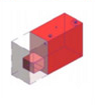
LOD 300

LOD 400

LOD 500

I hope this clarifies what different LOD levels represent in terms of geometry and information. Let’s discuss next how LOD is used on projects.
How LOD is used on projects
As mentioned earlier in this blog article in my definition, LOD specification is useful for many purposes during the project design, construction and operation phases.
Let’s briefly investigate how it is used in these phases.

Design phase
LOD specifications in design is used for the following purposes (this is not a comprehensive list):
- CODE COMPLIANCE - LOD geometry and information can be double-checked against local codes to ensure compliance to municipal, provincial, state, federal and environmental codes, standards, norms and certifications.
- CLASH DETECTION - LOD geometry can be used to run clashes between model elements, which include hard clashes (i.e. elements touching each other geometrically), soft clashes (i.e. elements within the space of clearances of each other geometrically), floating elements (i.e. elements that are floating in the model in a non-logical way).
- PARENT-CHILD RELATIONSHIP - LOD information can be used to understand the interrelationship between building elements (i.e. the source equipment of a kitchen sink) and correlation between systems (i.e. fire protection interface with plumbing system).
- COST ESTIMATION - LOD information can be used for cost estimation, by entering cost codes to model elements and getting cost estimates based on quantity takeoff.
- DESIGN OPTIMIZATION - LOD geometry and information can be used to optimize the design by having numerous iterations with handily available information of model elements (i.e. quick iterations of shadow studies on buildings.)
- SUSTAINABILITY - LOD geometry and information can be used to capture, define, refine and cross-link sustainability-related information of model elements (i.e. quick analysis of building materials.)
- QUALITY CONTROL - LOD geometry and information can be used to conduct quality control on design elements to ensure they work well together, and they communicate design intent effectively (i.e. 2D and 3D mullion details of curtain wall system).
Construction phase
LOD specifications in construction is used for the following purposes (this is not a comprehensive list):
- FABRICATION AND ASSEMBLY - LOD geometry and information can be used to develop, refine and communicate fabrication details to fabricators for fabrication and assembly (i.e. millwork)
- CONSTRUCTABILITY - LOD geometry and information can be used to develop, analyze, refine and communicate constructability of designs in real life (i.e. ensuring MEP equipment fit through wall openings during construction).
- SCHEDULING (4D) - LOD geometry and information can be used to develop, refine and communicate construction sequences on construction sites (i.e. order of installation of systems based on their type.)
- COST ESTIMATION (5D) - LOD information can be used for cost estimation, by entering accurate cost codes to model elements and getting cost estimates based on quantity takeoff.
- PROCUREMENT - LOD geometry and information can be used for procuring, provisioning or sourcing materials, equipment or labor to construction sites (i.e. raw material calculation for specific structural elements.)
- RISK ANALYSIS - LOD geometry and information can be used to conduct risk analysis by cross-linking and correlating the geometry and information of building elements (i.e. fire protection considerations on site)
Operations & maintenance (O&M)
LOD specifications in operations is used for the following purposes (this is not a comprehensive list):
- OPERATIONAL OPTIMIZATION – LOD geometry and information can be used to analyze, improve and optimize building operation (i.e. track performance and efficiency of building systems)
- OPERATIONAL LIFECYCLE COST – LOD geometry and information can be used to analyze and optimize the operational cost of the replacement of building elements based on their useful life (i.e. replacement cost of lighting fixtures over useful life of building.)
- MAINTENANCE, REPAIRS, REHABILITATION, REPLACEMENT – LOD geometry and information can be used to compare, analyze, manage, optimize and execute maintenance (i.e. servicing of building components), repairs (i.e. fixing building components), rehabilitation (i.e. fixing and putting building components back in service) and replacement (i.e. replacing with a new building component). This is extremely powerful and cost-effective if used correctly (i.e. comparative analysis of repairing vs replacing building equipment), and existing standards such as COBie can be used here.
- SUSTAINABILITY – LOD geometry and information can be used to analyze, improve and optimize building operational sustainability (i.e. automatic lighting schedule monitoring.)
- SECURITY – LOD geometry and information can be used to analyze, improve and optimize safety, security and access control of buildings (i.e. live monitoring of rooms.)
There are many other uses of LOD specifications for building projects, but the list above provides a good understanding of the benefits and the applications of LOD at a high level.
Let’s discuss an important distinction next between the British and the American definitions of LOD.
LOD in the United Kingdom vs United States

So the bottom line is, the US refers to LOD as “Level of Development” while the UK refers to LOD as “Level of Detail”. Is there a difference, and if so, what is it?
According to United BIM (source: United BIM):
“LOD is usually interpreted as a Level of Detail instead of Level of Development. This specification uses the concept of Level of Development. There are important differences.
Level of Detail is actually what proportion detail is enclosed within the model element. Level of Development is the degree to which the components’ specification, geometry, and attached information have been thought through – the degree to which project team members may depend on the information when using the model.
In essence, the Level of Detail can be thought of as input to the element, while the Level of Development is a reliable output.”
Also, ReBIM explains this difference clearly (source: REBIM) :
“In America, LOD refers to Level of Development. The American Institute of Architects (AIA) publicized (and trademarked) the term “levels of development” in AIA E202-2008: Building Information Modelling Protocol Exhibit, published in 2008. Since then, LOD – Level of Development is the degree to which the element’s geometry and attached information has been thought through. Later published Level of Development Specification published by BIM Forum in 2013 based on AIA protocols became base point of reference of several BIM Guidelines and documents in countries including Germany, France, Australia, Canada, China, Singapore and Taiwan.
In the UK, LOD is the commonly known acronym for Level of Detail. This was introduced within BIM Protocol released by AEC (UK) in 2009 as Level of Detail/Grade within its Model Development Methodology. Later in 2013 PAS 1192-2 Specification for information management for the capital/delivery phase of construction projects using building information modelling (now replaced by BS EN ISO 19650) introduced ‘Level of Definition’ as a new classification system with seven levels (1-7) to include both aspects of ‘Level of Model Detail’ (LOD) and Level of Model Information’ (LOI).” (source: REBIM)
The following table compares both LOD definitions and their equivalencies in UK and US terms (source: REBIM):
UK LOD
US LOD
Description
Content
1
Brief
A model communicating the performance requirements and site constraints. Building models would be block models only.
2
LOD 100
Concept
Conceptual or massing model including basic areas and volumes, orientation and cost. In the RIBA Plan of Work, this is equivalent to stage 2.
3
LOD 200
Developed design
A design development model, “generalized systems with approximate quantities, size, shape, location and orientation.” Equivalent to RIBA stage 3.
4
LOD 300
Production
Equivalent to RIBA stage 4. Production, or pre-construction, “design intent” model representing the end of the design stages. Modelled elements are accurate and coordinated, suitable for cost estimation and regulatory compliance checks.
5
LOD 400
Installation
Model suitable for fabrication and assembly, with accurate model of the construction requirements and specific components, including specialist sub-contract geometry and data.
6
LOD 500
As-built
An “as-built” model showing the project as it has been constructed. The model and associated data is suitable for maintenance and operations of the facility.
7
In-use
Asset Information Model used for ongoing operations, maintenance and performance monitoring.
And that’s it! Now we know everything about LOD, with some additional worldwide context.
Final thoughts
The Level of Development (LOD) is a useful tool for specifying geometry and information of BIM model elements for uses in the design, construction and operation phases of building projects. It definitely can add value by ensuring a common understanding among project stakeholders of what the project requirements and client expectations are. The most important uses of LOD specifications are the carryover of geometry and information between project phases, from design to construction, and from construction to operation.
However, like pretty much anything else in life, there can be a downside. LOD specifications can become a hurdle and a counterproductive tool if used incorrectly or relied on to micromanage building model elements. It can amount to a waste of time if model elements are developed to their full extent and not used for their intended purposes. Therefore, it is important to ensure that project stakeholders set out their commitments in proposals and contracts, and carry them out during project phases, so maximum benefits are reaped on projects.
The greatest takeaway here for LOD specifications is to be pragmatic and always bear the intended use in mind. If that intended use vanishes or changes over time, the LOD specifications or requirements should vanish or change as well.
Best of luck to all and I hope this article cleared things up regarding many aspects of LOD in BIM.
Thank you for taking the time to read my blog article and I’ll see you again soon.

Tarek Ghazzaoui, Eng.
Senior BIM Manager
Share now!
Resources
- SI Facilities - BIM model content – Level of Development matrix (downloadable)
- GSA - Model progression matrix (downloadable)
- Future USAP - Level of Development matrix
- NATSPEC National BIM Guide - BIM Object/Element Matrix Manual v1.0 (downloadable)
- BIM Forum - LOD Specification 2020 Part II (downloadable)
Works cited
“Bim Level of Development: LOD, 100, 200, 300, 350, 400, 500: Bim Modeling Services: Architecture Engineering and Construction(AEC): AEC Industry.” Srinsoft Inc, www.srinsofttech.com/bim-level-of-development-lod-300-400-500.html.
For Building Information Models and Data 20 … – Bimforum. https://bimforum.org/resources/Documents/LOD%20Spec%202020%20Part%20I%202020-12-31.pdf.
Document A121™ – 2018 – Help.aiacontracts.org. https://help.aiacontracts.org/public/wp-content/uploads/2020/12/AIA-A121_2018-sample.pdf.
“Bim Level of Development: Lod 100, 200, 300, 350, 400, 500.” United BIM, 20 Aug. 2021, www.united-bim.com/bim-level-of-development-lod-100-200-300-350-400-500/.
“Level of Detail.” GSA, 13 Aug. 2017, www.gsa.gov/real-estate/design-construction/3d4d-building-information-modeling/guidelines-for-bim-software/document-guides/level-of-detail.
October 30, 2015 – BIM International. https://bim-international.com/wp-content/uploads/2016/03/LOD-Specification-2015.pdf.
Admin_bim. “Levels of Detail – Lod.” BIM&CO, www.bimandco.com/bim/en/learn-more/levels-of-detail-lod.
“Level of Detail or Development: Lod in Bim.” REBIM®, 16 Sept. 2020, https://rebim.io/level-of-detail-or-development-lod-in-bim/.
About the author

Tarek Ghazzaoui, Eng. (senior BIM manager)
- 2d, 3d, articles by Tarek, featured, geometry, level of development, level of information, lod, lod 100, lod 200, lod 300, lod 400, lod 500, lod matrix, matrix